説明
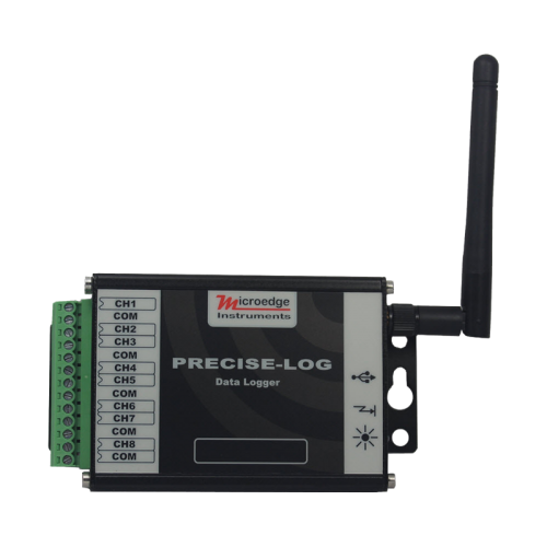
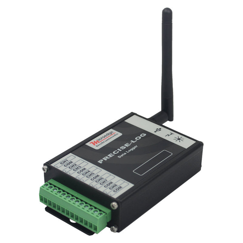
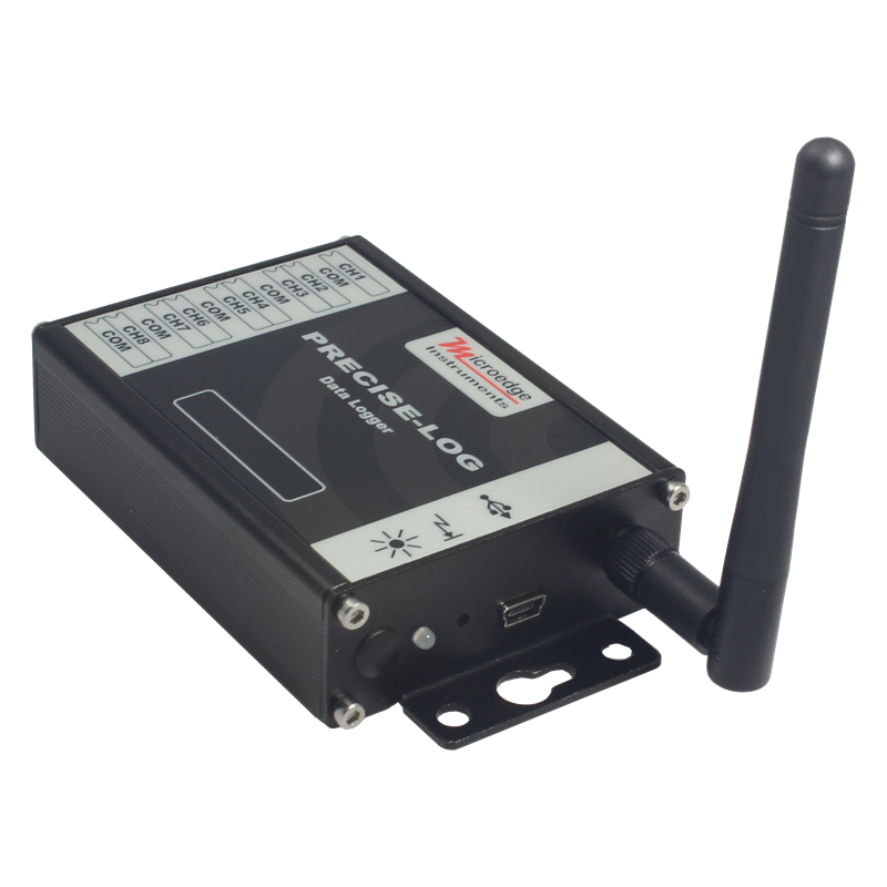
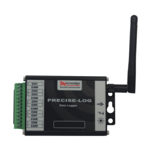
商品名: 無線電圧データロガー
メーカー: MICROEDGE INSTRUMENTS (CANADA)
シリーズ: PRECISE-LOG
モデル: PL-VW
PL-VWは、8チャンネル、バッテリ駆動、スタンドアロンおよびWIFI対応の電圧データロガーです。ロガーは8つの外部電圧源を記録し、8 MBメモリにデータを保存します。
そのアルミニウムエンクロージャーはそれを最も過酷な産業環境で優秀にします。
内蔵WIFIモジュールにより、リモートデータの監視とダウンロードが可能です。
16ビットADCは、正確で正確な測定が重要な科学および実験室のアプリケーションに最適です。
WIFIカバーエリアでロガーの電源を入れて、設定、ダウンロード、グラフ表示などのためにコンピューターからアクセスしてください
特徴:
- 8ch
- 16ビットA / Dコンバータ
- 8メガバイトのメモリサイズ
- USBとWIFIの両方が通信します。ボーレート115200 bpsのインターフェース
- プログラム可能な入力範囲(5 VDC、20 VDC)
- 10年以上のバッテリー寿命
- 設定、ダウンロード、プロット、分析、およびアラーム報告のための強力なソフトウェア
- 広いサンプリング間隔の選択(1秒から12時間)
- 頑丈なアルミ製筐体
Modbus
2019年7月15日から、Modbus TCPプロトコルがすべてのPRECISE-LOGシリーズのデータロガーに追加されます。Modbusマスタ/クライアントは、Modbus TCP通信を介してPRECISE-LOGデータロガーで利用可能な1つ以上の入力レジスタと保持レジスタを読み取ることができます
The below specifications list all supported commands and available registers PL-VW data logger supports:
Input Registers:
An Input Register stores a 16-bit integer for a channel’s real-time reading. To read one or more 16-bit Input register data, use function code 4.
| Register |
Description |
Type |
Range |
| 0 |
CH0 Value |
Unsigned Integer |
0 – 65535 |
| 1 |
CH1 Value |
Unsigned Integer |
0 – 65535 |
| 2 |
CH2 Value |
Unsigned Integer |
0 – 65535 |
| 3 |
CH3 Value |
Unsigned Integer |
0 – 65535 |
| 4 |
CH4 Value |
Unsigned Integer |
0 – 65535 |
| 5 |
CH5 Value |
Unsigned Integer |
0 – 65535 |
| 6 |
CH6 Value |
Unsigned Integer |
0 – 65535 |
| 7 |
CH7 Value |
Unsigned Integer |
0 – 65535 |
Example:
To read CH2, CH3 and CH4’s real-time values, a Modbus master device sends in the following command:
| Data(HEX) |
Description |
Note |
| 0001 |
Transaction identifier |
Fixed 2-byte value |
| 0000 |
Protocol identifier |
Fixed 2-byte value |
| 0006 |
Length(6 bytes are followed) |
2-byte value |
| 01 |
The device address |
1-byte value, don’t care |
| 04 |
Function Code (read Input Register) |
1-byte value |
| 0002 |
First register’s address |
2-byte value |
| 0003 |
The number of required registers (read 3 registers 0002 to 0004) |
2-byte value |
Holding Registers:
A Holding Register stores a 16-bit integer indicating a setting for the data logger. To read one or more 16-bit Holding Register data, use function code 3.
| Register |
Description |
Type |
Range/Equation |
| 0 |
Sample Interval |
0: below 1 second
>=1: sample interval in second |
0 – 65535 seconds |
| 1 |
Device Operating Mode |
0: logging stopped
1: logger is logging data |
|
| X0 |
CHX-1 Type |
0: Range#0 (0 to 20 VDC)
1: Range#1 (0 to 5 VDC)
2: Range#2 (-5 to +5 VDC) |
|
| X1 |
CHX-1 Enabled |
0:disabled
1:enabled |
If a channel is disabled, the reading is unknown |
| X2 |
CHX-1 Equation |
0: Range#0 Voltage |
Range: 0 to 20 VDC
Equation
O = 20 * I / 65535 |
| 1: Range#1 Voltage |
Range: 0 to 5 VDC
Equation:
O = 5 * I / 65535 |
| 2: Range#2 Voltage |
Range: -5 to +5 VDC
Equation:
O = 10 * I / 65535 – 5 |
| 3: Linear |
O = (LRH – LRL) * I / 65535 + LRL
Where:
LRH is Linear Range high value
LRL is Linear Range low value
You can get those values from SiteView |
Where X = 1,2,3,4,5,6,7,8
O = Output, I = Input Register Value
Example:
To read CH3’s equation, a Modbus master device sends in the following command:
| Data(HEX) |
Description |
Note |
| 0001 |
Transaction identifier |
Fixed 2-byte value |
| 0000 |
Protocol identifier |
Fixed 2-byte value |
| 0006 |
Length(6 bytes are followed) |
2-byte value |
| 01 |
The device address |
1-byte value, don’t care |
| 03 |
Function Code (read Holding Register) |
1-byte value |
| 002A |
First register’s address (42 is 2A in HEX) |
2-byte value |
| 0001 |
The number of required registers (read 1 registers 002A) |
2-byte value |
Note:
- Modbus feature was added to firmware version 2.05 or above.To upgrade a data logger’s firmware please refer to this link: How can I upgrade logger firmware?
- The age of an Input Register data is based the data logger’s sample interval.If the logger has stopped logging or the logger’s sampling interval is slower than five seconds, a request of Input Register data will initiate the sampling process and the new data will be available upon the next request.
